
Abstract
This article provides a comprehensive, systematic methodology for troubleshooting Dorma automatic doors governed by a Dorma controller. It addresses the need for a structured diagnostic process, moving from initial safety protocols and sensory inspections to the nuanced interpretation of error codes and LED indicators specific to models like the ES200. The examination extends to the methodical testing of peripheral components, including input sensors and output devices like motors and locks, to isolate the fault's origin. It further explores advanced diagnostics, such as parameter adjustments within the controller's software and firmware considerations, differentiating between hardware failure and configuration errors. The objective is to empower facility managers, maintenance professionals, and technicians with the analytical capabilities to accurately diagnose issues, determine if the Dorma controller itself is the point of failure, and confidently select and install appropriate replacement parts. This approach emphasizes a deep understanding of the system's integrated nature, promoting efficient repairs and long-term operational reliability.
Key Takeaways
- Always begin any diagnostic work by completely de-energizing the door system for safety.
- Interpret the controller's LED indicators and error codes as its primary diagnostic language.
- Systematically test external sensors and motors to rule them out before condemning the controller.
- Verify software parameters, as incorrect settings can mimic hardware failure.
- A faulty dorma controller should only be diagnosed after all other components are cleared.
- When replacing a controller, ensure the model number matches for seamless integration.
- Perform a commissioning cycle after installation for proper door calibration.
Table of Contents
- Step 1: Foundational Assessment and Safety Protocols
- Step 2: Decoding the Dorma Controller’s Language
- Step 3: Systematic Component Testing
- Step 4: Advanced Diagnostics and Parameter Adjustment
- Step 5: Sourcing and Replacing the Dorma Controller
- Frequently Asked Questions (FAQ)
- Conclusion
- References
Step 1: Foundational Assessment and Safety Protocols
The impulse to immediately tinker with a malfunctioning automatic door is a natural one, born from a desire to restore order and functionality. Yet, a reasoned and methodical approach, grounded in safety and careful observation, yields far more effective results. Before any tool is lifted or any wire is touched, the initial phase of troubleshooting must be one of patient assessment. This is not a passive step; it is an active process of gathering evidence, establishing a baseline, and ensuring the well-being of both the technician and the building's occupants. Think of yourself not as a mere repair person, but as a forensic investigator arriving at the scene. Your first responsibility is to secure the area and understand the situation as it stands, undisturbed. This foundational work prevents further damage, protects against injury, and provides the essential clues needed to solve the puzzle of the malfunction.
The Primacy of Safety: De-energizing the System
Within the ecosystem of Dorma automatic sliding doors, the Dorma controller operates with electrical potentials that are hazardous. The voltages required to actuate a heavy door panel, power sensors, and engage electric locks are sufficient to cause severe injury or worse. Consequently, the absolute first and non-negotiable action before any physical inspection of the controller or its connected components is to completely and verifiably de-energize the entire system. This act of rendering the system electrically safe is a moral and professional obligation.
The process begins by locating the dedicated circuit breaker in the building's electrical panel that supplies power to the automatic door. This breaker should be switched to the "off" position. A crucial secondary step is to apply a lockout/tagout (LOTO) device. This physical lock prevents anyone from inadvertently re-energizing the circuit while you are working. The accompanying tag clearly communicates that the system is undergoing maintenance and must not be touched. Many modern installations also include a local disconnect switch near the door header itself. If present, this should also be turned to the off position. The final verification involves using a multimeter set to measure AC voltage to test the incoming power terminals at the door's main connection point. Only when the meter reads zero volts can you be certain that the system is safe to work on. This deliberate, multi-step process may seem time-consuming, but it is the bedrock of safe practice in the field of electromechanical repair.
A Sensory and Visual Inspection: What to Look For
With the system safely powered down, the investigation can begin. This phase relies on your senses to detect abnormalities that a purely technical analysis might miss. It is a process of developing a feel for the machine's state of health.
Begin with a visual sweep of the entire door assembly. Look at the controller itself. Are there any obvious signs of physical damage to the casing? Do you see any discoloration, particularly browning or blackening, on the circuit board or around specific components? These are often tell-tale signs of overheating, where a component has exceeded its thermal limits. Pay close attention to capacitors, which can sometimes bulge or leak an electrolyte fluid when they fail.
Next, use your sense of smell. A sharp, acrid odor, often described as "burnt electronics," is a strong indicator that a component like a resistor, transistor, or integrated circuit has failed catastrophically. This scent can linger long after the initial event, providing a powerful clue. Conversely, the absence of such a smell does not rule out an electronic failure, but its presence almost certainly confirms one.
Carefully examine all wiring connections to the controller's terminal blocks. Are all wires firmly seated? A loose wire can cause intermittent faults that are notoriously difficult to diagnose. Look for frayed insulation or exposed copper, which could lead to short circuits. Trace the wiring as best as you can to connected devices like the motor, sensors, and locks, looking for any signs of pinching, kinking, or damage along the path. Also, inspect the environment within the door header. Is there any evidence of water ingress, such as rust stains, mineral deposits, or dampness? Electronics and moisture are incompatible, and even a small leak can lead to corrosion and failure of the Dorma controller.
Documenting the Initial State
Before you move, disconnect, or adjust anything, it is profoundly important to document the scene. In our modern age, the most powerful tool for this is the smartphone in your pocket. Take clear, well-lit photographs of the controller, its wiring connections, and the surrounding components from multiple angles. Capture the position of any switches or jumpers on the controller board. This visual record serves several purposes.
First, it creates a "before" state. If your troubleshooting steps inadvertently create a new problem, you have a reference to restore the original configuration. It is surprisingly easy to forget which wire went to which terminal amidst the complexity of a repair. Second, these images are invaluable if you need to consult with a colleague or a technical support specialist. Being able to share a clear picture of the situation is far more effective than trying to describe it verbally. Third, this documentation forms part of a professional service record. For facility managers overseeing multiple assets, having a visual history of a unit's condition can inform future maintenance schedules and purchasing decisions. This simple act of documentation transforms a reactive repair into a proactive data-gathering exercise, elevating the quality of the maintenance process.
Step 2: Decoding the Dorma Controller’s Language
A modern Dorma controller is more than just a switchboard; it is an intelligent device with its own internal logic and diagnostic capabilities. It constantly monitors its own status and the state of all connected peripherals. When a problem arises, it does not simply cease to function; it actively communicates the nature of the fault. Learning to interpret this communication is the most direct path to an efficient diagnosis. This involves understanding its specific vocabulary of error codes, the grammar of its flashing lights, and how to navigate its internal menus. To the untrained eye, a blinking light is just a blinking light. To the informed technician, it is a sentence, a paragraph, a clear statement of the problem at hand.
Understanding Error Codes and LED Indicators
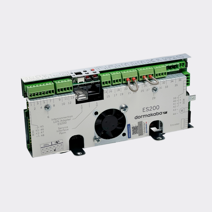
The most immediate form of communication from a Dorma controller, such as the widely used ES200, is through its onboard Light Emitting Diodes (LEDs) and, on some models, a digital display that shows specific error codes. These are not cryptic signals; they are a purpose-built diagnostic language. Typically, a solid green light indicates that the controller is powered on and operating normally, in a state of readiness. Any deviation from this—be it a red light, an orange light, or a flashing pattern—signals a specific condition or fault.
For example, a flashing red light might indicate a safety sensor obstruction, while a solid red light could point to a more serious internal hardware fault. The key is to understand that the manufacturer has programmed these signals with specific meanings. These meanings are detailed in the product's technical manual, which should be considered an essential reference text. Attempting to diagnose a fault without consulting the manual's error code table is like trying to understand a foreign language without a dictionary. Below is a representative table of common diagnostic indicators for a controller like the Dorma ES200. Note that specific codes can vary slightly based on firmware versions, reinforcing the need to consult the manual for your exact unit.
| LED Indicator / Error Code | Potential Meaning | Initial Diagnostic Action |
|---|---|---|
| Solid Green LED | Normal operation; system is ready. | No action needed. The system is functioning as expected. |
| Flashing Green LED | System is in a special mode (e.g., night bank). | Verify the program switch setting. Ensure it's not in an unintended mode. |
| Solid Red LED | Internal controller fault or critical error. | Cycle power to the system. If the error persists, the controller may need replacement. |
| Flashing Red LED (1x) | Primary safety sensor (internal) is active. | Check for obstructions in the door's path. Clean the sensor lenses. |
| Flashing Red LED (2x) | Secondary safety sensor (external) is active. | Check for obstructions in the door's approach area. Verify sensor alignment. |
| Error Code F4 | Motor error or obstruction. | Check for physical obstructions. Check motor wiring and test motor function. |
| Error Code F8 | Communication error with programming unit. | Check the connection cable between the controller and the handheld programmer. |
| Error Code F9 | Main control module fault. | This often points to a definitive failure of the Dorma ES200 main control module. |
Accessing the Diagnostic Menu
Beyond the basic LED indicators, many Dorma controllers offer a more profound level of interaction through a digital display and navigation buttons, or via a connection to a handheld programming unit. This interface is the gateway to the controller's brain, allowing you to move beyond interpreting signals to actively interrogating the system.
Imagine the door is failing to open. The LED indicator might simply show a generic fault. By accessing the diagnostic menu, you could navigate to a screen that shows the real-time status of all inputs. You might see, for example, that the "Activation Sensor" input reads "Active" even when no one is near the door. This immediately shifts your focus from a potential motor or controller problem to a faulty or miscalibrated sensor that is sending a constant "open" signal. The diagnostic menu can provide a wealth of information, including:
- Input/Output Status: A live view of whether each sensor, lock, and switch is active or inactive.
- Cycle Count: The total number of times the door has opened and closed, which is invaluable for understanding its usage history and planning preventative maintenance.
- Error Log: A history of the last several fault codes, which can help diagnose intermittent problems that are not present when you are on site.
- Component Values: Readings such as motor current or voltage, which can indicate if the motor is straining due to a mechanical issue.
Learning to navigate these menus is a skill that dramatically accelerates troubleshooting. It allows you to use the controller itself as your primary diagnostic tool, leveraging its own intelligence to pinpoint the source of the problem with precision.
The Role of the User Manual: Your Primary Text
In an age of online forums and video tutorials, the humble user manual is often overlooked. This is a significant mistake. For a complex piece of equipment like a Dorma controller, the official technical manual provided by the manufacturer is the single most authoritative source of information (DORMA, 2011). It is the constitution upon which the entire system is built.
The manual contains not just the error code tables mentioned earlier, but also detailed wiring diagrams, specifications for input and output voltages, and step-by-step procedures for configuration and commissioning. Different firmware versions of the same controller model may have subtle but important differences in their parameters or diagnostic readouts. The manual specific to your unit is the only way to be certain of the correct information. It provides the ground truth.
Treat the manual as a text to be studied, not merely glanced at. Before beginning a complex diagnosis, take the time to read the relevant sections. Understand the intended function of each terminal and the logic of its operation. This foundational knowledge, derived directly from the source, empowers you to move beyond guesswork and apply a truly analytical and effective troubleshooting methodology. A technician who has mastered the manual is equipped to solve problems that would baffle others.
Step 3: Systematic Component Testing
Once you have interpreted the initial messages from the Dorma controller, the next logical phase of investigation is to verify the integrity of the components that communicate with it. A controller's decision-making is only as good as the information it receives from its sensors and its ability to command its actuators. A fault in an external device can often present as a controller error, leading to a costly and unnecessary replacement. Therefore, a process of systematic isolation and testing is fundamental. This is akin to a doctor testing a patient's reflexes and hearing to determine if a neurological problem originates in the limbs, the sensory organs, or the brain itself. You must methodically test the system's "senses" (inputs) and "muscles" (outputs) to determine if the fault lies with them or with the central "brain"—the controller.
Isolating the Controller: The Process of Elimination
The core principle here is to simplify the system to its most basic state. An automatic door system is a network of interconnected devices: motion sensors, safety beams, push buttons, electric locks, and the motor. A fault in any one of these can send an erroneous signal to the controller, causing it to behave unpredictably. The most effective way to diagnose this is to disconnect these peripheral devices one by one.
Start with the non-essential components. For instance, if the system has both an overhead motion sensor for activation and a push-plate, disconnect the motion sensor first. After disconnecting it, cycle the power to the controller and see if the fault clears. If it does, you have successfully isolated the problem to that sensor or its wiring. If the fault remains, reconnect the sensor and move to the next component, perhaps the electric lock. By methodically disconnecting, testing, and reconnecting each device, you can systematically eliminate variables. If you disconnect all external inputs and outputs, leaving only the power supply and the motor connected, and the fault code still appears on the controller, you have gathered strong evidence that the issue is likely internal to the motor or the controller itself. This process of elimination is a powerful diagnostic technique that prevents you from chasing phantom problems and focuses your attention where it is needed most.
Testing Input Devices: The Eyes and Ears of the System
Input devices are the senses of the automatic door. They include activation sensors (like BEA microwave or infrared sensors), safety beams that detect obstructions, and manual activation switches. A failure in one of these can feed the Dorma controller false information. Testing them requires a basic understanding of electronics and the use of a multimeter.
Most sensors and switches operate on a "dry contact" principle, meaning they function like a simple switch, either creating a closed circuit or an open circuit. To test this, you can use the continuity setting on your multimeter. After disconnecting the sensor's signal wires from the controller, you can test the sensor directly. For a motion sensor, for example, the contacts should show an open circuit (no continuity) when there is no motion, and a closed circuit (the multimeter will beep) when you move in front of it. If the sensor's contacts are permanently stuck open or closed, the sensor has failed.
For safety beams, the logic is often reversed. The beams create a closed circuit when they are aligned and unobstructed. If someone or something breaks the beam, the circuit opens, sending a signal to the controller to stop or reverse the door. You can test this by checking for continuity at the terminals while the beam is clear, then blocking the beam with your hand and confirming that the circuit opens. If it does not behave as expected, the problem lies with the safety beams, not the controller. This methodical testing of each input provides definitive proof of its operational status.
Evaluating Output Devices: The Muscles of the System
The primary output devices in an automatic door system are the motor, which provides the force to move the door, and any electric locking mechanisms. The Dorma controller sends voltage to these devices to make them act. Evaluating them involves checking if the controller is sending the correct signals and if the devices are responding.
To test the motor output, you can use a multimeter set to measure DC voltage. With the motor disconnected from the controller, you can carefully connect your multimeter probes to the motor output terminals on the controller itself. Then, trigger the door to open (you may need to temporarily connect an activation switch). You should see the controller output a specific voltage, typically 24V DC, for a set period. If the controller outputs the correct voltage, but the motor (when reconnected) does not turn, the problem is likely with the motor or its connection. If the controller fails to output any voltage, it suggests a failure in the controller's motor drive circuit. This is a critical diagnostic step that clearly separates a controller fault from a motor fault.
Similarly, the output for an electric lock can be tested. When the door is supposed to be unlocked, the controller should send a specific voltage (e.g., 12V or 24V DC) to the lock terminals. If that voltage is present, but the lock does not disengage, the lock itself is the likely culprit. If the voltage is absent, the issue lies within the controller's logic or output relay. This clear demarcation is essential for accurate diagnosis.
To help conceptualize these failure points, consider the following comparison:
| Component Type | Common Failure Modes | Diagnostic Clues |
|---|---|---|
| Input Devices | Stuck contacts (open/closed), sensor misalignment, lens contamination, internal electronic failure. | Constant activation signal, failure to detect presence, persistent safety fault code on controller. |
| Output Devices | Motor burnout, worn motor brushes, seized gearbox, failed lock solenoid, broken wiring. | Humming or grinding noises, door fails to move despite voltage output, lock fails to engage/disengage. |
By systematically working through the inputs and outputs, you build a comprehensive picture of the system's health, allowing you to confidently narrow down the source of the malfunction.
Step 4: Advanced Diagnostics and Parameter Adjustment
After confirming that the external components and their wiring are sound, the investigation must turn inward, toward the mind of the machine itself: the software and nuanced electrical states of the Dorma controller. Many issues that appear to be catastrophic hardware failures are, in fact, solvable problems of configuration or power quality. This level of diagnosis requires a shift in perspective from the mechanical to the logical. It involves interrogating the controller's programming, considering the integrity of its operating firmware, and scrutinizing the quality of its power source. This is where a technician's deep knowledge separates them from a parts-swapper, allowing for elegant solutions that can restore function without requiring expensive hardware replacement.
Diving into the Programming Parameters
Every action the automatic door takes—its opening speed, the force it uses, how long it stays open, how gently it closes—is dictated by a set of adjustable parameters stored in the Dorma controller's memory. These settings are the personality and operating instructions for the door. An incorrect or corrupted parameter can cause behavior that perfectly mimics a mechanical or electronic fault.
Consider a door that slams shut with excessive force. The immediate assumption might be a failure in the motor's braking mechanism or a fault in the controller's motor control circuit. However, it is equally possible that the "braking distance" or "closing speed" parameter has been set incorrectly. Perhaps a previous technician, in an attempt to solve another issue, changed a value without understanding its full implication. Or, in rare cases, a power surge could have corrupted a memory location, altering a key parameter.
Using the handheld programmer or the onboard interface, a skilled technician can access and review these parameters. The process involves:
- Reading the Current Parameters: Before making any changes, download or write down all existing settings. This creates a backup, allowing you to revert to the original state if your adjustments do not solve the problem.
- Comparing to Defaults: The technical manual will list the factory default settings. Comparing the door's current parameters to these defaults can often highlight a value that is far outside the normal range.
- Making Incremental Adjustments: If a parameter seems suspicious, adjust it in small, logical increments. For example, if the closing speed seems too high, reduce the parameter value by 10% and then run a test cycle. Observe the door's behavior. Does it improve? Does it get worse? This iterative process of adjustment and observation is a core tenet of system tuning.
By approaching the parameters with a methodical and cautious mindset, you can often resolve complex behavioral issues. A door that refuses to lock might not have a broken lock or controller, but simply have the "locking function" parameter set to "off." A door that seems sluggish could have its "motor power" setting too low. This exploration of the controller's software is a powerful, non-invasive diagnostic tool.
Firmware Considerations and Updates
The firmware is the embedded operating system of the Dorma controller. It is the fundamental software that runs the hardware and interprets the user-defined parameters. Just like the operating system on a computer or smartphone, firmware can sometimes contain bugs or be improved over time. Manufacturers may release firmware updates to fix known issues, improve performance, or add new features.
In some cases, a persistent and unexplainable issue that cannot be traced to hardware or parameters may be a known firmware bug. This is particularly true for newer models or features. Checking the manufacturer's website or technical bulletins for information related to your controller's model and firmware version (which can be found in the diagnostic menu) can sometimes reveal that the problem you are facing has already been identified and solved with a software update.
The process of updating firmware is a delicate operation that should only be undertaken if you are confident in the procedure and have the correct tools. An interruption during a firmware update (like a power loss) can potentially "brick" the controller, rendering it permanently inoperable. However, for a persistent software-related problem, a firmware update can be the only solution short of replacing the entire unit. It is an advanced technique, but one that is part of a comprehensive diagnostic toolkit.
When to Suspect the Power Supply Unit (PSU)
The Dorma controller is the brain, but the Power Supply Unit is the heart, pumping the lifeblood of electricity throughout the system. The PSU is responsible for taking the high-voltage AC power from the wall and converting it into the stable, low-voltage DC power that the controller's sensitive electronics require. A failing PSU can cause some of the most confusing and intermittent problems imaginable.
A PSU does not always fail completely. It can fail "softly," providing a voltage that is slightly too low or unstable. This condition, known as a "brownout," can cause the controller's microprocessor to behave erratically. It might reset randomly, lose its parameter settings, or throw false error codes. The symptoms can look exactly like a controller failure, leading to a misdiagnosis.
To diagnose a PSU issue, you need a multimeter capable of accurately measuring DC voltage.
- Test Under Load: Simply testing the PSU's output with nothing connected can be misleading. The voltage might look fine. The true test is to measure the voltage while the door is in operation—this is testing it "under load."
- Look for Voltage Drop: Connect the multimeter to the PSU's output terminals. Trigger the door to open. As the motor starts to draw current, watch the voltage reading on your meter. A healthy PSU should maintain a stable voltage with only a very small drop. If you see the voltage sag significantly (e.g., a 24V supply dropping to 18V), the PSU is struggling to provide the necessary power and is likely failing.
- Check for AC Ripple: An advanced test involves setting your multimeter to measure AC voltage on the DC output. A healthy DC supply should have a negligible amount of AC "ripple." A reading of more than a few millivolts of AC can indicate failing capacitors within the PSU, which can cause instability in the controller.
Suspecting the PSU is a mark of an experienced technician. It demonstrates an understanding that the controller is part of a larger electrical ecosystem, and its health is dependent on the quality of the power it receives. Replacing a faulty PSU is often a simpler and less expensive repair than replacing the entire controller.
Step 5: Sourcing and Replacing the Dorma Controller
After a meticulous process of elimination—having ruled out external components, confirmed software parameters, and verified the integrity of the power supply—you may arrive at the definitive conclusion: the Dorma controller itself is the source of the failure. This diagnosis is not a guess; it is a reasoned judgment based on evidence. At this point, the focus shifts from diagnosis to resolution. This involves correctly identifying the required replacement part, making an informed choice about sourcing it, and executing the replacement and subsequent commissioning with precision. This final act restores the system to full functionality and validates the entire diagnostic effort that preceded it.
Making the Final Diagnosis: When the Controller is the Culprit
Confidence in condemning the controller comes from the rigor of your previous steps. You can be certain the controller has failed when you observe the following conditions concurrently:
- The controller displays a specific internal fault code (like a "Main Control Module Fault" or a solid red "fail" light) that does not clear after a power cycle.
- All external input and output devices have been disconnected from the controller, yet the fault persists. This confirms the fault is not being caused by a peripheral device.
- The incoming power from the Power Supply Unit has been measured and confirmed to be stable and at the correct voltage, even under load.
- The controller fails to provide a voltage output to a specific device (like the motor or lock) when commanded, even though the diagnostic menu indicates it should be active.
- The controller is completely unresponsive, with no lights or display, despite having verified power at its input terminals.
When these conditions are met, you have effectively isolated the fault to the controller's internal circuitry. The problem is not in its senses, its muscles, or its food source; the problem is in its brain. This confident diagnosis prevents the costly mistake of replacing a healthy controller and gives you the mandate to proceed with sourcing a new one.
Selecting the Right Replacement Part
Once the decision to replace the controller is made, the most critical detail is selecting the exact correct part. The world of automatic door parts is one of precise model numbers and subtle variations.
- Identify the Exact Model Number: Look for a label on the casing of the old Dorma controller. You will find a specific model number, such as "ES200," "ES 200 Easy," or "CS 80 MAGNEO." You may also find a part number. These identifiers are not interchangeable. A controller for one system will not work on another.
- Note the Firmware Version: If possible, note the firmware version from the controller's diagnostic menu before removing it. While often compatible, sourcing a replacement with a similar or newer firmware version can prevent unexpected compatibility issues with existing peripherals.
- Consider Sourcing Options: You generally have two primary paths for sourcing a replacement. You can seek out a genuine, original-brand part directly from the manufacturer or an authorized distributor. This guarantees 100% compatibility. Alternatively, you can explore high-quality replacement parts from specialized suppliers. These components are often designed to be fully compatible and meet or exceed original specifications, sometimes offering a more readily available or cost-effective solution. For a common and robust unit, a high-quality ES200 controller replacement part can provide reliable performance and a direct fit, ensuring a smooth installation process. The choice depends on factors like urgency, budget, and availability.
Making the correct selection is paramount. Installing the wrong controller can, at best, simply not work, and at worst, potentially damage other components in the system like the motor or power supply.
The Installation and Commissioning Process
With the correct replacement controller in hand, the final step is the physical installation and the crucial commissioning process.
- Safety First: Reconfirm that the system is fully de-energized and locked out.
- Label Everything: Before disconnecting a single wire from the old controller, label each wire with a piece of tape indicating which terminal it connects to (e.g., "MOT+", "SEN1," "GND"). Taking a final set of photos is also a wise precaution. This labeling is the single most effective way to prevent wiring errors during reinstallation.
- Swap the Units: Carefully disconnect all the wires and remove the old controller from its mounting. Install the new controller in its place.
- Reconnect with Care: Following your labels, reconnect each wire to the corresponding terminal on the new controller. Ensure each connection is snug and secure. A loose connection is a future failure point.
- Initial Power-Up: Once all wiring is double-checked, remove your lockout/tagout device and restore power to the system. The new controller should power on and likely enter a default or error state, as it has not yet been programmed.
- Commissioning (The Learning Cycle): This is the most important part of the installation. The new controller knows nothing about the door it is attached to. The commissioning process, often initiated by holding a button or through a menu command, puts the controller into a "learning" mode. During this cycle, the controller will slowly open and close the door one or more times. It is measuring the door's weight, its travel distance, and the friction in the system. It uses this data to automatically calculate and set optimal parameters for opening speed, closing force, and braking points. This ensures the door operates both efficiently and safely, in compliance with standards like ANSI/BHMA A156.10.
Skipping the commissioning cycle is a recipe for poor performance and potential safety hazards. Once the learning cycle is complete and the door is operating smoothly, the repair is finalized. You have successfully navigated the entire process from suspicion to solution.
Frequently Asked Questions (FAQ)
What are the most common signs of a failing Dorma controller?
The most common signs include the door behaving erratically or intermittently, the door becoming completely unresponsive, a solid red fault light on the controller that won't clear after a power reset, or specific error codes on the display that point to an internal hardware or memory failure.
Can I repair a Dorma controller board myself?
Repairing the internal circuit board of a Dorma controller is generally not recommended for anyone other than a trained electronics specialist with soldering and component-level diagnostic experience. The boards often contain microprocessors and surface-mount components that require specialized tools. For most technicians and facility managers, replacing the entire controller unit is the safer and more reliable solution.
How often should a Dorma controller be serviced?
While the controller itself is a solid-state device with no moving parts, the system it manages should be professionally inspected and serviced at least annually, in line with manufacturer recommendations and safety standards like ANSI/BHMA A156.10. This service would include checking controller parameters, inspecting wiring, and testing all connected safety devices, ensuring long-term reliable operation.
Is a universal controller a good replacement for a Dorma one?
A universal controller can sometimes be used, but it often requires significant rewiring and programming, and may not support all the specific features of the original Dorma system (like proprietary sensor communication). For a direct-fit and reliable repair, using a genuine Dorma part or a high-quality, fully compatible replacement designed specifically for your model is strongly recommended to ensure seamless integration and performance.
What tools do I need to troubleshoot my automatic door system?
A basic troubleshooting kit should include a good quality multimeter (for testing voltage and continuity), a set of insulated screwdrivers (both Phillips and flat-head), wire strippers, and a set of nut drivers or wrenches. A smartphone for taking pictures for documentation is also invaluable. For more advanced diagnostics, a handheld programming unit specific to the controller is often necessary.
My door is moving very slowly. Is it the controller?
A slow-moving door can be caused by several factors. While it could be a parameter setting within the Dorma controller (like "opening speed" being set too low) or a fault in the controller's motor drive, it is also commonly caused by external issues. These include low voltage from a failing power supply, increased physical resistance from worn carriage wheels or a misaligned track, or a failing motor. You must test these other components before concluding the controller is the sole cause.
Conclusion
Successfully troubleshooting a Dorma controller is not a matter of luck or guesswork; it is the application of a logical, evidence-based process. By embracing a methodology that begins with safety, moves through careful observation and interpretation, and proceeds with the systematic testing of each part of the system, one can move from a state of uncertainty to one of diagnostic clarity. Understanding the controller as the central nervous system of the door—a device that listens to inputs, processes information, and commands outputs—is foundational. This perspective allows a technician to distinguish between a problem with a sensor, a motor, a setting, or the controller itself. The ability to decode its language of error codes, to probe its software parameters, and to verify the quality of its electrical supply transforms a repair from a simple replacement of parts into a sophisticated act of problem-solving. This disciplined approach not only ensures an accurate and efficient repair but also deepens one's understanding of the intricate dance between hardware and software that brings an automatic door to life.